Earth Retention

Earth Retention systems are utilized to protect adjacent streets, buildings, utilities, etc. while an excavation takes place. Typically used methods are soldier pile and wood lagging, sheet piles, shotcrete & soil nails, tangent walls and secant walls. These systems can either be cantilevered, tied back or internally braced depending upon the wall height and soil conditions. They can also be structurally permanent or temporary, based upon the final construction requirements.

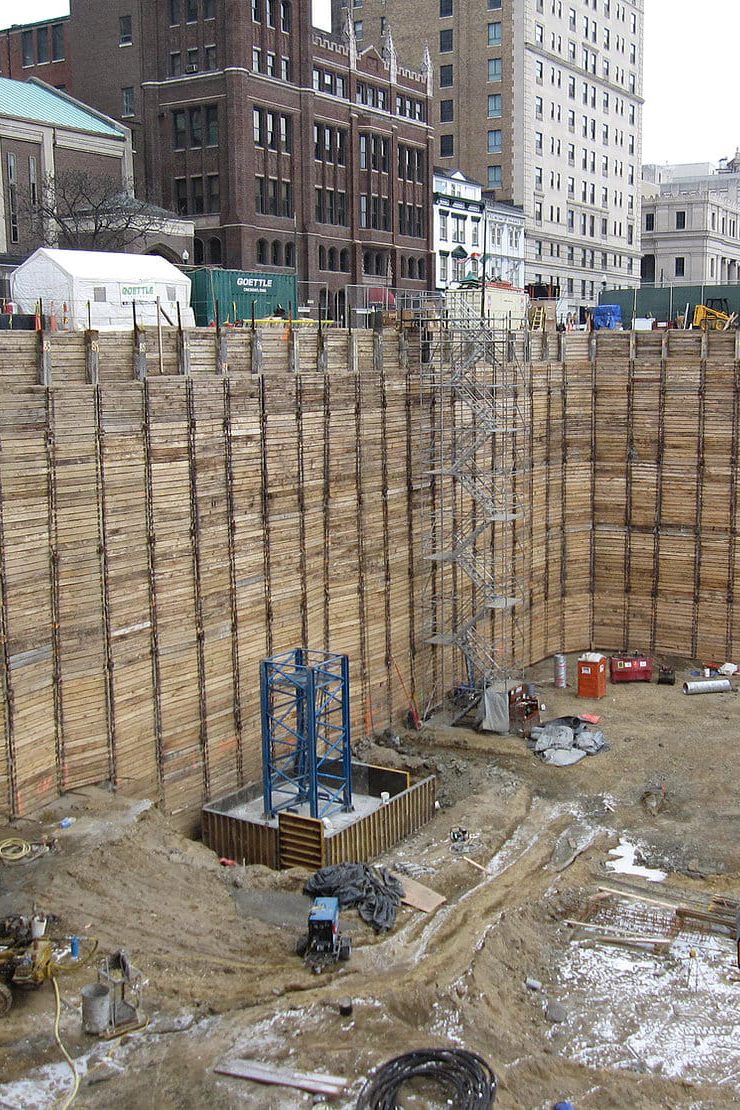
Soldier pile and wood lagging is a widely used and effective earth retention system. Soldier piles are drilled or driven at regular intervals along the perimeter of the excavation. Once the excavation starts, wood lagging is installed to maintain the excavated face. Soldier pile walls can cantilever or be laterally braced to suit the specific needs of the project.

Location

Atlanta, GA

Project Facts

80 EA - drilled piers ranging in diameter from 36” - 96”
20,000 SF - wood lagging shoring with drilled-in soldier piles

Scope

Design-Build temporary earth retention and drilled pier deep foundation for new parking deck.

Location

Cincinnati, OH

Project Facts

7,400 SF - Earth retention with untreated wood lagging
60 EA - HP12X53 at 35’ in length
43 EA - Temporary Tieback Anchors

Scope

Design-Build temporary earth retention system for the construction of a new residential tower and parking garage.

Location

Toledo, OH

Project Facts

18,800 SF - Temporary earth retention with untreated wood lagging
83 EA - Drilled in soldier piles at 35’- 45’ in length
98 EA - 14” diameter auger ties at 40’ in length

Scope

Design-Build temporary earth retention system for the ozone treatment facilities to be installed at Collins Park Water Treatment Plant.

Location

Vincennes, IN

Project Facts

31 EA - drilled-in soldier piles
31 EA - rock tieback anchors
Exposed wall height: 21’

Scope

Furnish and install permanent earth retention system to stabilize tracks along riverside.

Location

Cincinnati, OH

Project Facts

5800 SF - Drilled in Soldier piles with permanent tieback anchors

Scope

Design-build permanent earth retention system and site wall for new building on church campus.

Location

Akron, OH

Project Facts

17,500 SF of temporary earth retention
110 EA - Driven Soldier Piles
110 EA - Tieback Anchors (Titan Bars)
275 EA - 16” diameter Tiedown Anchors at 45’ in length

Scope

Designed, furnished and installed a temporary earth retention system to allow for the excavation of the proposed CSO Basin.
Also, Goettle designed, furnished, installed, and tested tiedown anchors using CFA methods.

Location

Great Smoky Mountains National Park - Swain Co., NC

Project Facts

44 - HP14 x 73 galvanized soldier piles - 40' avg. length
114 - DCP 4 strand tieback anchors - 50' avg. length
7500 SF untreated temporary wood lagging
7500 SF precast concrete lagging

Scope

Design and installation of +/- 7500 SF of permanent tied back earth retention consisting of drilled in soldier piles, temporary wood lagging, permanent tieback anchors and permanent precast concrete lagging.

Location

West Union, WV

Project Facts

Value engineered design - build (soldier pile wall)
75 pre-drilled soldier piles
115 DCP tie-back anchors
25,000 SF of precast concrete lagging panels
56' maximum wall height

Scope

Install 718 LF of permanent rock and soil retention system consisting of soldier piles, precast concret panels, and tie-back anchors
The wall originally designed as a soil nail wall

Location

New Albany, IN

Project Facts

74ea. - pre-drilled soldier piles
119ea. - permanent tie-back anchors
26,000 SF of earth retention
47' maximum wall height
70,000 CY of excavation

Scope

Installed 710 LF of permanent rock and soil retention system consisting of soldier piles, concrete facing and tie-back anchors
Soils consisted of 10' of overburden clay, with hard shale for the remainder of the height

Location

Augusta, KY

Project Facts

10,056 man hours
4,800 SF shotcrete
1,500 LF rock bolts
13,200 SF driven PZC-14 sheet piles 25' to 90' in length

Scope

24 12x53x50' H piles and 10,000 SF temporary earth retention
248 link belt
Dawson 2400 Hammer
rented 110-ton crane on barge
rented Delmag drill
138 link belt crane

Location

Dayton, OH

Project Facts

41 soldier beams placed utilizing 24" diameter using continuous flight auger
41 40' long 52/16 TEI Anchors
9,200 Sq. Ft. Wood Lagging
41 ea. 14x85 36' tangent piles @ 16" diameter auger
30 ea. #9 Gr 60 bar, 36' tangent piles @ 16" diameter auger
Bracing at the top of both walls

Scope

Installation of 9,200 Sq. Ft. of temporary earth retention with 41 tieback anchors, and 79 tangent piles @ 16" in diameter

Location

Dayton, OH

Project Facts

1700 SF of soil nail / shotcrete underpinning
2900 SF soldier pile wood lagging

Scope

Installation of permanent soldier piles with wood lagging including tiebacks and 17,000 SF of soil nail and shotcrete underpinning

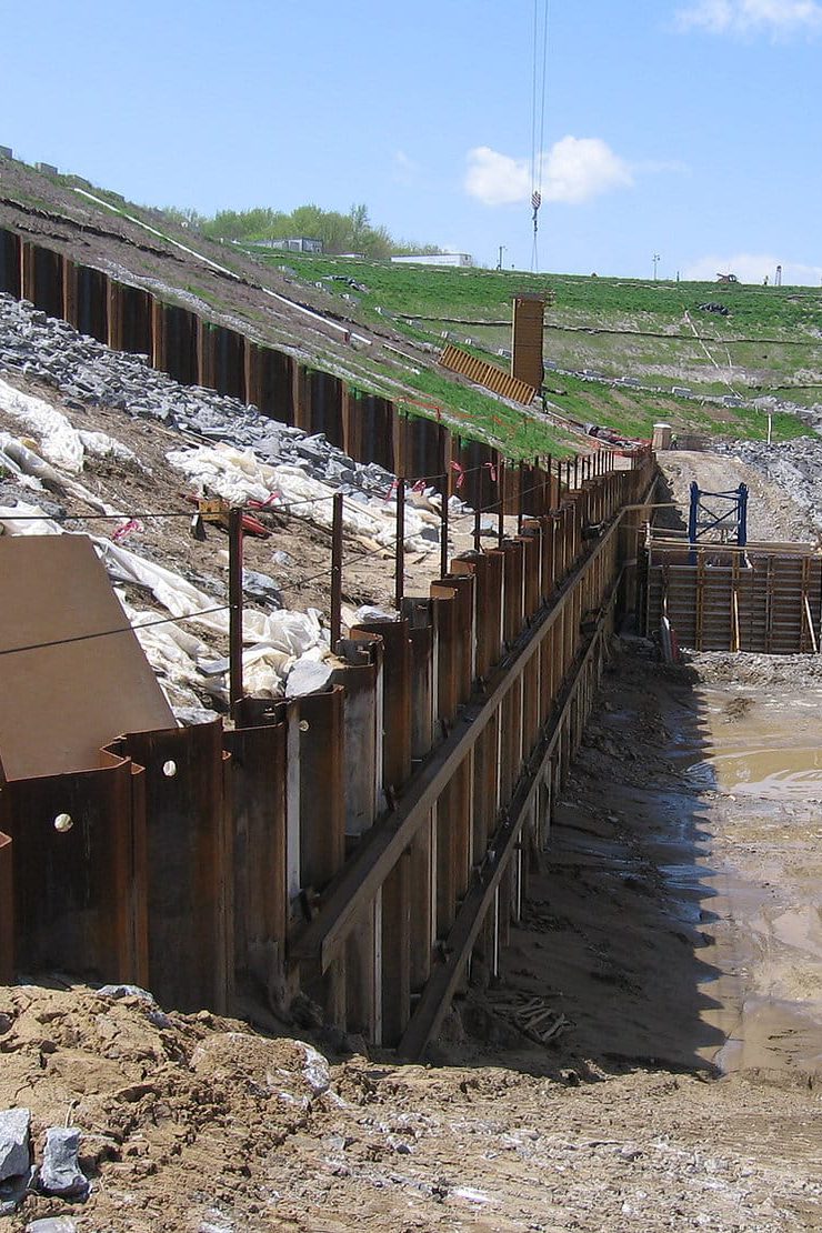
When the retained soil cannot be de-watered, a sheet pile earth retention system is an effective solution. Sheet piles are steel sections in a wide variety of cross-sectional shapes – all with the ability to interlock with one another forming a continuous, watertight wall. The sheets are driven or vibrated into the ground. Cantilever walls are typical, but the sheet piles can be laterally braced to suit the specific needs of the work site. Being manufactured from steel, they offer a high strength material with excellent quality control.

Location

Cincinnati, OH

Project Facts

Phase 1:
140 EA - sheet piles at 80’ length with internal bracing
144 EA - tieback Anchors
Approx. 60’ exposed cut height

Phase 2:
162 EA - sheet piles at 60’-70’ with 2,800 LF of internal bracing
60 EA - tieback anchors
2 EA existing 10’ diameter sewer piles
40’-50’ exposed cut height

Scope

Design-build temporary sheet pile earth retention system for a new diversion concrete structure and interconnecting piping to support future work of a new pump station.

Location

Cincinnati, OH

Project Facts

230 LF of Driven sheet piles and soldier piles with tieback anchors

Scope

Furnish and install permanent earth retention system to protect existing utilities from soil erosion.

Location

Lake Charles, LA

Project Facts

Sheet piles at an average of 40'
Work started in October 2015
Projected completion: August 2016
Man hours to date: 20,654
Estimated man hours at completion:37,500

Scope

Installation and extraction of 40' sheet piles by three crews using Linkbelt 218 HSL's x 3 with 44-50 ICE vibratory hammers

Location

New Orleans, LA

Project Facts

Build 11' - 62' dia. cells
Build 3' - 38' dia. cells
Installation of 90,000 tons of cell fill
3,500 tons PS-31 sheets

Scope

Install North and South cofferdam for installation of new Seagate Complex
Complete to project schedule of 20 weeks

Location

Panama City, Panama

Project Facts

17,000 tons PS-31 sheets
230,000 cubic meters of cell fill
1,400 tons PZC-26 sheets
221,000 cubic meters dredging

Scope

Design-Build project
Installed 24' - 72' dia. cells
Installed 34' - 58' dia. cells
Construct 1,500 LF of bulkhead retaining wall
Completed to project schedule of 38 weeks

Location

Clermont County, OH

Project Facts

Installed 12 54" diameter caissons drilled 40' into rock for uplift resistance of the 7' thick tremie seal
5 levels of W36x300# ring walers provided lateral support for cofferdam during dewatered state
15,765 Sq. Ft. of sheet piles 95 ft. in length

Scope

54' octagon shapped cofferdam with caissons drilled 40' into rock, dewatered 80' below the lakes pool elevation including walers for support when dewatering
This was the installation of the deepest single wall dewatered cofferdam ever constructed, design by Douglas Keller, P.E. of Goettle

Location

Augusta, KY

Project Facts

10,056 man hours
4,800 SF shotcrete
1,500 LF rock bolts
13,200 SF driven PZC-14 sheet piles 25' to 90' in length

Scope

24 12x53x50' H piles and 10,000 SF temporary earth retention
248 link belt
Dawson 2400 Hammer
rented 110-ton crane on barge
rented Delmag drill
138 link belt crane

Location

Columbus, OH

Project Facts
Scope

Installation of sheet piles and micropiles to stabilize bridge foundation and abutment in Columbus, Ohio for CSX.

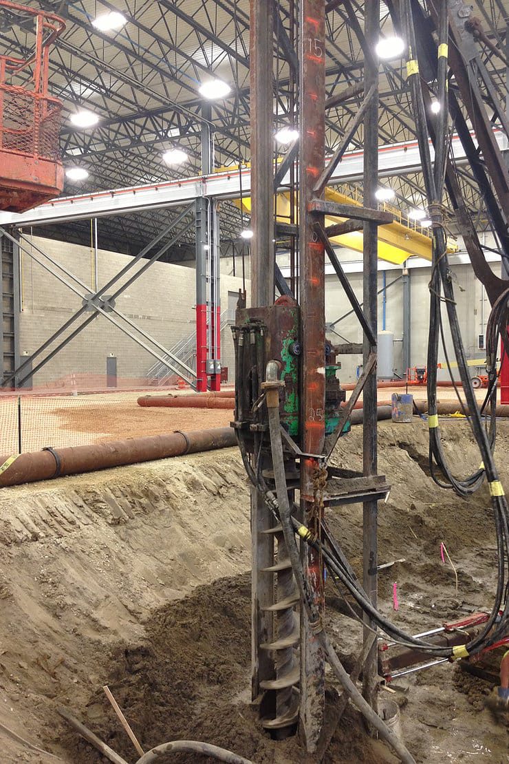
When an excavation takes place next to an existing structure, a secant or tangent pile wall can be an excellent solution. Tangent & secant walls are a series of interlinking or adjacent concrete drilled piers or piles installed along the perimeter of the excavation. This method of earth retention not only allows for a high degree of alignment flexibility, it provides a structurally stiff wall, which minimizes settlement concerns of the adjacent structures.

Location

Columbus, OH

Project Facts

668 EA - 1180 mm and 1200 mm diameter secant piles at 70-90’ length
Primary piles installed via CFA methods
Secondary piles installed with sectional casing
Total wall is 2,200 LF
Responsible for surveying and spoil removal

Scope

Design-assist partner for a partial cutoff wall and retaining/cutoff wall for a new stadium.

Location

Binghamton, NY

Project Facts

131 EA - 1,500 mm x 36’ Secant Piles
11 EA - 1,500 mm x 45’ Secant Piles
17 Caissons - 30” diameter, 35’-40’ in length 235 tons of reinforcing steel

Scope

Installation of 17 caissons and 142 secant piles.
Project was performed with a BG40 and BG-39 drilling simultaneously on a 200’x100’ site.
Piles were installed through sand and clay overburdens with the casing and tooling advanced through 17,000 PSI share and limestone.

Location

Miamisburgh, OH

Project Facts

64 EA - 1,500mm x 55' long Secant Piles
Drilled through sands, boulders/cobbles up to 36" in diameter
Drilled with BG-40 while oscillator and crane concreted and pulled casing

Scope

Design-Build permanent earth retention system for waste treatment facility expansion.
Restricted site - 75' x 100' footprint

Location

Binghamton, NY

Project Facts

142 Secant Piles 5' Dia., 20' - 40' in length
17 Caissons at 30" Dia., 35' - 40' in length
235 tons re-inforcing steel
Started March 2016, est. completion July 2016

Scope

Installing secant piles at 5' Dia. along with 17 Caissons at 30" Dia. in Vestal, New York for the Binghamton Sewage Treatment Plant
Equiptment used on site: Goettle's BG 40 and a BG39 alongside a Maxim 218 Link Belt Crawler Crane

Location

Cleveland, OH

Project Facts

6,000 Sq. Ft. of temporary earth retention
Including bracing
Support of four utilities

Scope

Installing temporary earth retention with bracing
Installing supports for four utilities while work was completed across a trench excavation

Location

Dayton, OH

Project Facts

41 soldier beams placed utilizing 24" diameter using continuous flight auger
41 40' long 52/16 TEI Anchors
9,200 Sq. Ft. Wood Lagging
41 ea. 14x85 36' tangent piles @ 16" diameter auger
30 ea. #9 Gr 60 bar, 36' tangent piles @ 16" diameter auger
Bracing at the top of both walls

Scope

Installation of 9,200 Sq. Ft. of temporary earth retention with 41 tieback anchors, and 79 tangent piles @ 16" in diameter

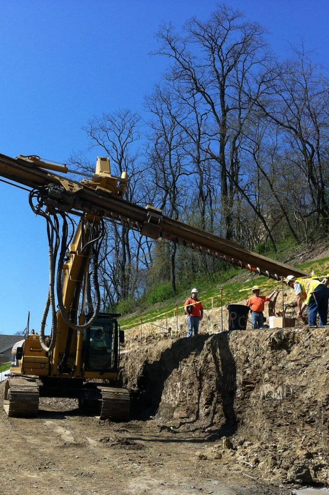
A soil nail wall is constructed from the top – down, excavating in lifts of about five feet. At each lift, a soil reinforcement element – a soil nail – is installed and shotcrete is applied to the exposed earth face. This process continues to the required depth. Once completed, a reinforced soil mass is in place to resist the lateral earth forces. This type of earth retention can follow nearly any alignment and can be constructed in any type of soil that can stand vertically for five feet for a work shift. Soil nailing employs relatively small installation equipment and is well suited for close quarters.

Location

West Lafayette, IN

Project Facts
Scope

39 drilled soldier piles with tieback anchors
7300 sq. ft. of wood lagging
1925 sq. ft. of soil nails and shotcrete underpinning

Location

Pittsburgh, PA

Project Facts

5,200 SF of soil nail wall
220 ea. - epoxy coated soil nails
8" thick shotcrete facing

Scope

Installed an earth retention system consisting of 5,200 SF of shotcrete and soil nails for the Burchick Construction Company

Location

Dayton, OH

Project Facts

1700 SF of soil nail / shotcrete underpinning
2900 SF soldier pile wood lagging

Scope

Installation of permanent soldier piles with wood lagging including tiebacks and 17,000 SF of soil nail and shotcrete underpinning

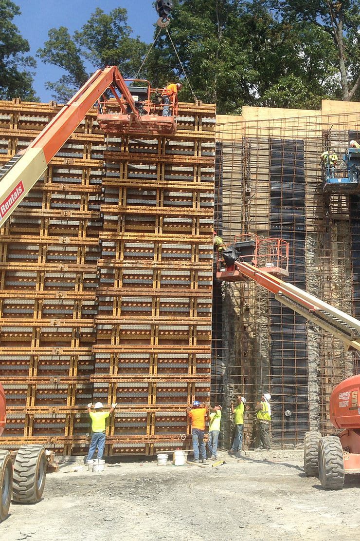
Integrated wall solutions combine that of permanent earth retention systems and in-situ concrete placement or the use of precast concrete panels. The first is to pour the liquid concrete material into forms against the existing PERS (Permanent Earth Retention System); this is so-called in-situ concrete. The other method used is called precase concrete, in which panels of specific size are manufactured in a central plant and later brought to the job site for fast, clean assembly.

Common applications of integrated wall solutions include; highway (DOT), railroad, retaining walls, bridge approaches and abutments.

Location

Great Smoky Mountains National Park - Swain Co., NC

Project Facts

44 - HP14 x 73 galvanized soldier piles - 40' avg. length
114 - DCP 4 strand tieback anchors - 50' avg. length
7500 SF untreated temporary wood lagging
7500 SF precast concrete lagging

Scope

Design and installation of +/- 7500 SF of permanent tied back earth retention consisting of drilled in soldier piles, temporary wood lagging, permanent tieback anchors and permanent precast concrete lagging.

Location

West Union, WV

Project Facts

Value engineered design - build (soldier pile wall)
75 pre-drilled soldier piles
115 DCP tie-back anchors
25,000 SF of precast concrete lagging panels
56' maximum wall height

Scope

Install 718 LF of permanent rock and soil retention system consisting of soldier piles, precast concret panels, and tie-back anchors
The wall originally designed as a soil nail wall

Location

New Albany, IN

Project Facts

74ea. - pre-drilled soldier piles
119ea. - permanent tie-back anchors
26,000 SF of earth retention
47' maximum wall height
70,000 CY of excavation

Scope

Installed 710 LF of permanent rock and soil retention system consisting of soldier piles, concrete facing and tie-back anchors
Soils consisted of 10' of overburden clay, with hard shale for the remainder of the height

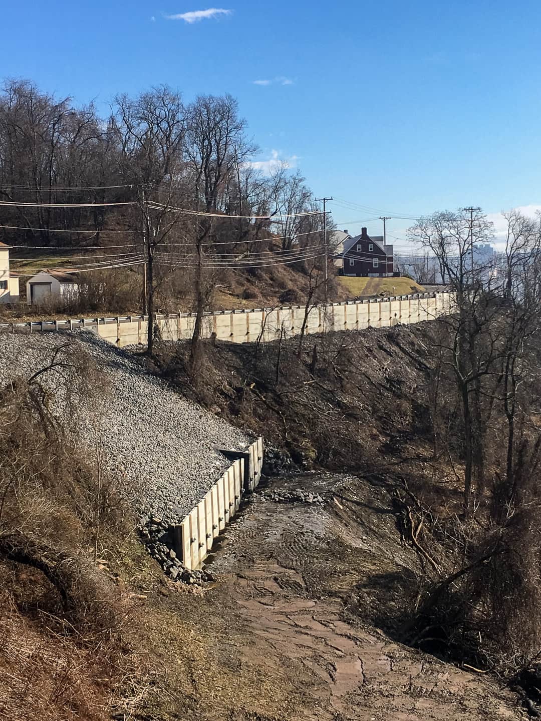
Slopes and embankments frequently experience settlement, stability and erosion problems. Richard Goettle, Inc. off­ers various solutions to these problems. From landslides to construction cuts into hillsides, remediation or an earth retaining structure is required to maintain the slopes’ stability.

Ground anchors, micro piles, anchored reaction blocks, and anchored retaining walls are all stability solutions that not only reinforce the soil but also control erosion. Anchored reaction blocks are ideal for newly failed slopes, applying loads to stabilize the soil. Ground anchors and micro piles create a stabilized ground reinforcement system which resists the driving forces of the slope. Anchored Retaining Walls are ground modification systems that include drilled or driven vertical elements that extend below potential failure planes. Drilled and grouted tieback anchors provide additional stabilization forces.

Location

Great Smoky Mountains National Park - Swain Co., NC

Project Facts

44 - HP14 x 73 galvanized soldier piles - 40' avg. length
114 - DCP 4 strand tieback anchors - 50' avg. length
7500 SF untreated temporary wood lagging
7500 SF precast concrete lagging

Scope

Design and installation of +/- 7500 SF of permanent tied back earth retention consisting of drilled in soldier piles, temporary wood lagging, permanent tieback anchors and permanent precast concrete lagging.

Location

West Union, WV

Project Facts

Value engineered design - build (soldier pile wall)
75 pre-drilled soldier piles
115 DCP tie-back anchors
25,000 SF of precast concrete lagging panels
56' maximum wall height

Scope

Install 718 LF of permanent rock and soil retention system consisting of soldier piles, precast concret panels, and tie-back anchors
The wall originally designed as a soil nail wall

Location

New Albany, IN

Project Facts

74ea. - pre-drilled soldier piles
119ea. - permanent tie-back anchors
26,000 SF of earth retention
47' maximum wall height
70,000 CY of excavation

Scope

Installed 710 LF of permanent rock and soil retention system consisting of soldier piles, concrete facing and tie-back anchors
Soils consisted of 10' of overburden clay, with hard shale for the remainder of the height